
Usually a rotor is axially symmetrical in design so that it is relative to the axis of rotation. However, due to the influence of a series of elements in the machining process, the final assembled rotor can not always achieve complete axially symmetrical drive force with a certain amount of imbalance. This kind of rotor imbalance is generally called initial imbalance.
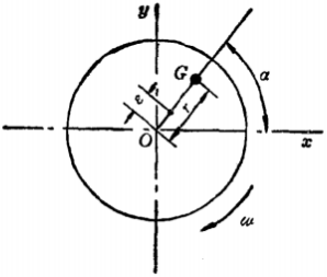
If a rotor is divided into thicknesses of Δ For the original z, there is an unbalance in each disc (as shown in Figure 1). Unbalanced mass identified as G exists at radius R and circumferential reference angle α Where the centrifugal force generated is:

In ω It is angular velocity. Visible centrifugal force F with ω The square increases. So the product of G and R becomes an unbalanced quantity and is generally expressed as |U| G r = (or abbreviated U = G r) in g/mm, then:

Therefore, the centrifugal force is proportional to the unbalanced quantity, which is a vector of direction and is usually expressed as:

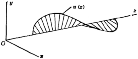
As the imbalance of each disc is different in size and direction (as shown in Fig. 2 and 3), the imbalance of the rotor is a function of the axis coordinates. Because the adjustment of impeller dynamic balance is emphasized in this paper, it is not described in detail.
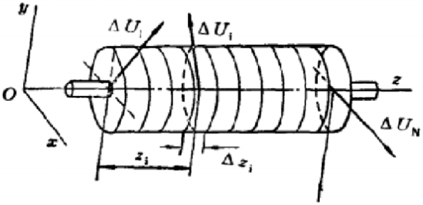
Figure 2: Unbalance of one rotor
1. Non-uniformity of rotor material:
2. Imbalance of coupling:
3. Imbalance caused by asymmetric keyway.
4. Some roundness errors and eccentricities will always occur in rotor machining.
5. Impeller imbalance hazard;
The imbalance caused by these factors is random and can not be calculated. Therefore, it must be measured and corrected according to gravity test (static balance) and rotation test (dynamic balance) to reduce it to the permitted level.
Reprint declaration: This article was originally edited by Shenman Balancing Machine Factory www.shshenman.com. It can not be reproduced without permission!


